
A collector does not create the separation shown in a chromatogram; it times the diversion of post-column liquid into identified receiving vessels. You will be able to set the trigger and delay, size the collection run, prevent carryover, and preserve each fraction for later analysis.
Key takeaways
- Set collection triggers from detector time, threshold, or peak windows.
- Match vessel positions to fraction volume and downstream sample requirements.
- Use rinsing, spacing, and controlled movement to limit carryover.
- Seal, label, inspect, and store fractions at conditions that protect stability.
How a chromatogram becomes a collection command
The fraction collection process begins after the column and mobile-phase conditions separate compounds into bands. The collector does not separate them; it diverts the detector’s post-column effluent into vessels. How fraction collectors work with collected samples depends on the trigger selected:
| Option | How it decides | Main trade-off |
|---|---|---|
| Fixed time | Collects during programmed time intervals | Predictable, but may collect blank solvent |
| Fixed volume | Switches vessels after a set volume passes | Consistent volume, but ignores peak location |
| Peak or threshold | Starts when the detector signal crosses a set level | Reduces blank collection, but depends on baseline stability |
| Slope-based | Responds to the signal’s rate of rise or fall | Detects changing peaks, but noise can cause false triggers |
In a peak-based sequence, the detector signal crosses the defined threshold, the collector waits through the configured delay, and collection starts. It stops when the signal falls below the threshold or the programmed peak-width rule is met.
Baseline drift, detector noise, solvent gradients, and thresholds set above a low-abundance peak can cause false starts, split peaks, or missed fractions.
Set the delay from the detector measurement point to the outlet tip. Include detector-cell and flow-cell volume, connecting tubing, valve volume, and outlet tubing. Delay time equals intervening volume divided by actual flow rate: at 2 mL/min with 0.8 mL between points, the delay is 0.4 minutes, or 24 seconds.
Verify it after changing flow rate, tubing, gradient timing, or system configuration.
How the collector moves each fraction into the right vessel
The fraction collectors operation begins when the controller moves the switching valve and positions a moving rack or dispensing head. The outlet aligns with the selected tube, bottle, or well, then dispenses until the programmed time or volume is reached. A laboratory fraction collector workflow therefore follows trigger, position, align, dispense, and switch.
Programmed volume equals flow rate multiplied by collection time: 10 mL/min × 1 minute gives a 10 mL target, not a guaranteed 10 mL recovery. Switching time, tubing holdup, retained outlet drops, splashing, and incomplete drainage change the volume that reaches the vessel.
| Configuration | Movement | Main control point |
|---|---|---|
| Moving rack | Tray moves beneath a fixed outlet | Vessel spacing and stopping clearance |
| Moving head | Outlet travels between stationary vessels | Head position and drip control |
| Valve plus motion | Flow switches while the rack or head moves | Divert transition liquid to waste |
The transition between vessels is finite. At high flow, liquid can enter the outgoing or incoming vessel unless waste diversion and adequate clearance are provided. Check rack layout, vessel spacing, usable rather than nominal capacity, headspace for foaming, and waste-vessel capacity.
- Route remaining effluent to waste.
- Stop or complete the method and record the final position.
- Lift or close the outlet so it cannot drip across the rack.
Collection preserves separation delivered by the column; it cannot resolve overlapping peaks after they leave the column.
How to stop adjacent fractions from contaminating one another
A separate vessel does not prevent carryover. Residue can remain in the detector-to-collector line, switching valve, outlet tubing, or dispensing tip, so moving to a clean rack does not clean the fluid path.
| Control point | Action | Failure prevented |
|---|---|---|
| Outlet position | Centre the tip over the vessel and maintain clearance from its rim | Drips, splashing, and contact transfer |
| Between collections | Send initial rinse and non-target effluent to waste | Contamination between selected peaks or time windows |
| Fluid path | Flush between runs with a solvent compatible with the method; clean or replace a contaminated tip | Persistent carryover |
| Vessel capacity | Compare programmed volume with usable volume, leave headspace, and check for splashing | Overflow into adjacent positions |
| Waste routing | Confirm the waste vessel can hold every diverted rinse and non-target fraction | Waste overflow and deck contamination |
A collector that captures only selected peaks saves vessel capacity and reduces solvent handling. It depends on a validated detector-to-outlet delay, however; keep flow rate and gradient timing unchanged, or recalculate the delay before collecting again.
Use this fraction collector sample handling record for every vessel:
- Link the run ID, rack or plate position, fraction number, trigger or time window, and solvent conditions.
- Record whether the fraction was pooled, and with which other positions.
- Reset the rack before reuse and verify the fraction map against the method.
In a reliable laboratory fraction collector workflow, discard the first rinse to waste, confirm outlet alignment, and watch the transition between vessels. A delayed switch, retained drop, or overflowing waste bottle can change sample identity even when the program itself is correct.
How to seal, inspect, and store collected samples
After liquid enters a tube, bottle, or well, fraction collector sample handling depends on a controlled handoff, not simply moving the vessel to a shelf. Verify the position against the run map, inspect volume and appearance, and check for bubbles, precipitate, splashing, or an incorrectly aligned outlet.
- Seal the vessel, remove it without disturbing neighbouring positions, and record the run ID, fraction number, and storage destination.
- Match the container and seal to the chemistry, then transfer the sample into validated storage.
- Check the outlet, wetted path, switching valve, rack, and waste line as well as the receiving vessel; carryover or extractables can enter before the sample reaches its container.
Material choice changes the result:
| Material | Solvent resistance and adsorption | Extractables and gas permeability |
|---|---|---|
| Glass | Strong resistance; low adsorption for many compounds, but fragile | Low extractables and low gas permeability |
| Polypropylene | Good general resistance; assess adsorption of hydrophobic compounds | Moderate extractables and gas permeability |
| Polyethylene | Useful for compatible aqueous systems; adsorption can affect hydrophobic compounds | Higher gas permeability than glass or fluoropolymer |
| Fluoropolymer | Excellent resistance and low adsorption | Low extractables and very low gas permeability |
For volatile mobile phases, use capped tubes or compatible plate seals, minimise headspace, and transfer promptly. A seal can obstruct pipetting or react with the solvent. Use amber vessels or light-blocking covers for light-sensitive samples; minimise headspace and exposure for oxygen-sensitive samples.
Viscous or corrosive samples need allowance for incomplete drainage and verified compatibility. For temperature-sensitive material, use a validated cooled rack or chamber, then transfer rapidly; cooling does not replace storage control and can cause condensation or ice.
That is how fraction collectors work with collected samples: collection preserves identity only when inspection, sealing, and storage complete the method.
How to choose capacity and configuration for downstream analysis
Choose the collection format around the next analytical step: define the expected number of fractions, fraction volume, peak width, flow rate, run duration, and whether you will pool adjacent vessels. These inputs shape the fraction collection process and the laboratory fraction collector workflow; fraction collectors operation is only reliable when vessel capacity matches the method.
| Format | Strength | Main limitation |
|---|---|---|
| Tubes or bottles | Larger usable volume; better for pooling, protected storage, and manual inspection | More handling and weaker positional identity |
| Microplates | Fixed positional identity; direct robotic transfer and assay compatibility | Limited well volume, greater evaporation exposure, and higher splash risk |
A tube-based method cannot move directly to a 96-well plate. Check well capacity, well spacing, outlet geometry, seal compatibility, and the collector’s motion path before changing format.
Use this selection check:
- Calculate required vessels as target fractions plus blank, rinse, and contingency positions.
- Confirm usable volume, not nominal volume, and leave headspace for foaming and switching losses.
- Check rack clearance, outlet alignment, and waste capacity for all diverted solvent.
- Match the format to HPLC or LC-MS injection, evaporation, assay transfer, or manual inspection: decide whether you need direct pipetting, protected storage, or pooling.
Septech Marketing LLP can help verify detector delay, wetted-part compatibility, rack geometry, valve timing, and the transfer path before you commit to a configuration. Recheck these points after changing flow rate, tubing, gradient timing, or collection format.
Related product
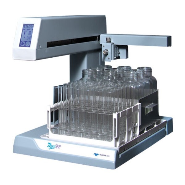
 | Chromatography Foxy® R1 Fraction Collector Compact, One-Rack Flexibility The Foxy® R1 is a one-rack fraction collector that adapts to a broad spectrum of... View product → |
Frequently asked questions
How does a chromatogram become a fraction collection command?
The collector uses a selected trigger, such as retention time, detector threshold, or a defined peak window, to divert effluent into a vessel.
How does a fraction collector move each sample into the correct vessel?
A programmed arm, carousel, rack, or valve positions the selected vessel beneath the outlet for the collection interval.
How do you prevent contamination between adjacent fractions?
Use accurate positioning, suitable spacing, controlled flow, rinsing between fractions, and enough vessel capacity to prevent overflow or splashing.
How should collected fractions be sealed and stored?
Inspect each vessel for volume, clarity, leakage, and correct labelling, then seal it and store it at the temperature and light conditions required for sample stability.
How do you choose fraction collector capacity and configuration?
Calculate the number of fractions, collection volume, vessel size, solvent compatibility, and downstream analysis needs before selecting racks, plates, tubes, or larger containers.